HP 304H Superheated Steam Piping
400 MW CCGT

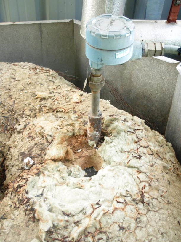
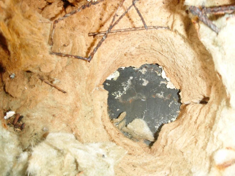
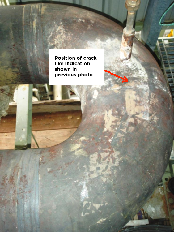
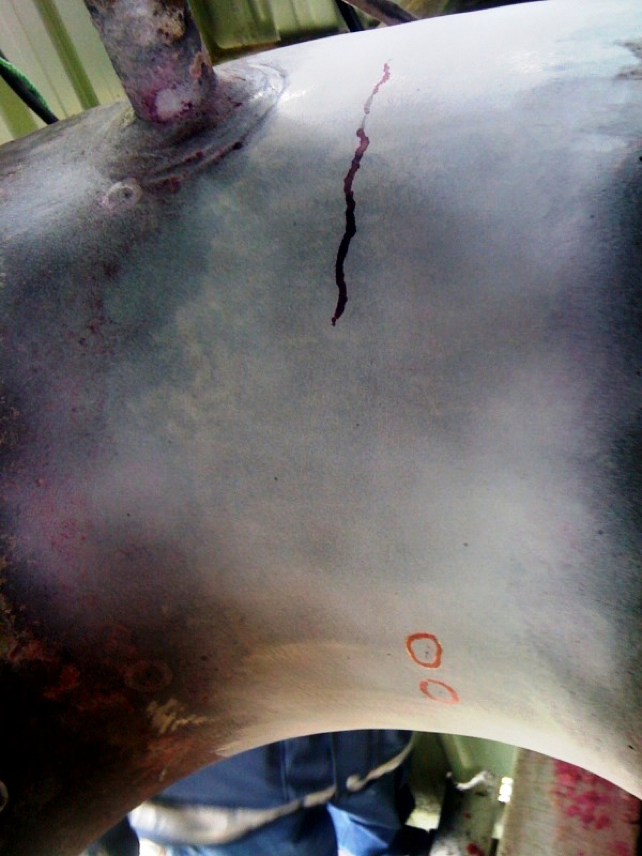
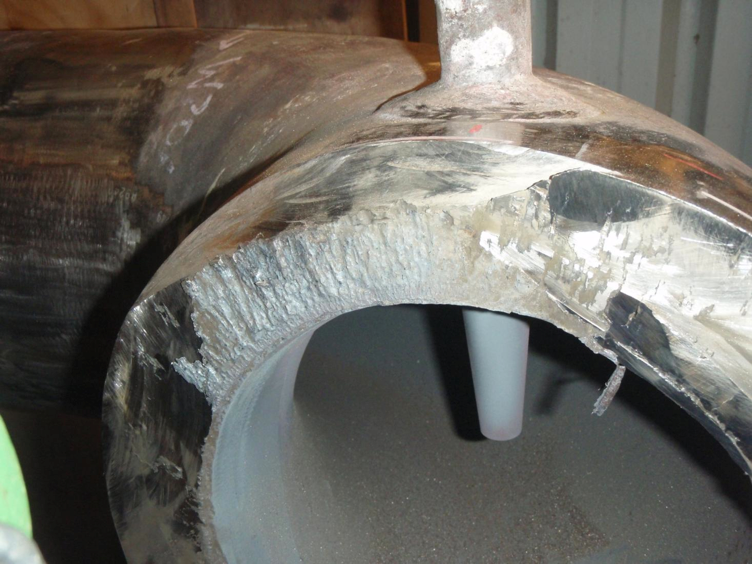
Our client’s operators identified a suspicious steam leak indication at the HP Steam line. The indication was very small and difficult to assess whether it was just rain water ingressing into the lagging and steaming off. Furthermore, the “leak” appeared to be at a thermowell and it was initially through to be, if a real steam leak, probably a small defect at the thermowell.
The client had decided to take the unit off line due to a period of low demand, so the opportunity was taken to open the lagging and remove the cladding to investigate.

Weld identification and datum protocols

After the lagging was removed, a hole was found in the insulation as shown in the photo above.  The hole wasn’t at the thermowell, it was adjacent to it.

A close up image of the hole in the lagging showed that there were weld beads at this location, indicating that there was a butt weld.  A circumferential oriented defect was also visible.  Maybe this was a crack like indication?

The elbow was stripped. It confirmed that there was a butt weld at the back to back 90 degree elbows. The drawings had indicated that there was no weld at this position. It was supposed to be a single 180 degree forged elbow.

After dressing off the weld cap and preparing the area for Penetrant Testing (PT), the extent of the surface breaking defect started to become apparent.  The photo above shows the findings from the PT.

A boat sample was removed to allow a partial analysis of the defect to be carried out.  The fracture face shown in the photo above shows the extent of the defect and the significant gouging that the superheater HP Steam at this location had done to the fracture faces.

The cross section from the boat sample showed the crack had evidence of cycling and was oxide filled.

PEI WERE ENGAGED BY OUR CLIENT TO:

• investigate the root cause of the failure
• identify the extent of this failure and whether any more piping was affected, i.e. nominate the penalty inspection regime
• Coordinate all inspection works carried out as a result of the penalty inspection regime, review results and determine if any additional repairs were required
• Determine the options for repair of the piping
• Advise on the future inspection programme for monitoring of a repeat failure if this was a possibility.
• Coordinate with all parties to get all decisions, investigation, repair works completed with the highest possible efficiency to allow the unit to return to service.

FINDINGS:

• HP Manifold was 350NB 48.64mm Thick, but the wall thickness at the cracked weld was significantly heavier than nominal thickness (approaching 70mm)
• Return 180 deg elbow, actually back to back 90 degree elbows, which was an un-documented weld
• Cracking was located just upstream of De-superheater, which had experienced overspray issues particularly during start up and shutdown in early days following commissioning
• Fatigue cracking was identified in the metallurgical failure analysis
• Investigation found cracking in 2 welds immediately downstream, which were also just upstream of the HP Desuperheater spraywater injection location

REPAIR METHODOLOGY

• Materials needed to be re-used as no replacement materials were available at short notice
• All old weld metal and heat affected zone was removed when preparing the materials for the repair
• The wall thickness at the 90 degree back to back elbow butt weld was dressed to minimise the excess wall thickness, which would assist in minimising the thermal fatigue at this location
• Nominated full thickness GTAW for the new 304H heavy wall welds in order to minimise grain size and improve UT testability
• Traditionally UT is limited on SS materials – developed new procedure, purchased new probes, welded a test block – this was to ensure that the new welds had minimal test restriction when inspecting for possible recurring defects.

Figure 1 (above) – 304H heavy wall HP Steam Line Steam Leak Repair showing damaged weld after removal of spool piece for reworking, removed spool included cracked welds requiring repair.

Figure 2 (above) – Shop spooling of elbow & reducer after cracked welds removed, reclaiming fittings and using full thickness GTAW weld process to minimise grain size and improve future inspection ability using UT methods.

OTHER INVESTIGATION

• A review of the desuperheater spray logic was carried out to determine whether there were any opportunities for overspray or thermal shock
• Check of the condition of the spraywater valves was carried out to verify if they were passing when closed.
• Temperature monitoring of the HP steam manifold metal temperature was carried out to evaluate temperature differential of metal compared with steam throughout the start up procedure.

The unit was able to be returned to service with confidence that any similar defects had been identified and addressed through the penalty inspection regime nominated as part of the investigation. The equipment was reinstated using updated weld procedures that would improve the inspectability of the welds in the future inspection programme. Baseline NDT was carried out on the new welds for future reference. The root cause of the failure was investigated. There was uncertainty that the root cause was properly identified but measures were put in place to minimise the risk of a repeat failure.
The findings were a very good reminder that all suspected steam leaks need to be carefully investigated and assumptions on the position from which they are originating should not be made until adequate inspection has been undertaken. Incorrect assumptions in this scenario may have resulted in a catastrophic failure if the leak had been allowed to progress to critical crack length.